Sunday 30 August 2020

Final Signal Install

 Signal Planting Complete

The install of the 46 signals is now complete with the last units being installed in Port Henry and Plattsburgh. The next step is to complete more testing. I think I have ironed out most issues, but with trains on the layout and "real world" testing,  I may find a few things I have missed. I know the dwarfs in Port Henry and Plattsburgh not exactly work the way I had planned but will now test and see.


Plattsburgh entering from the South.


Plattsburgh departing from the South.


Plattsburgh Entering from the North


Port Henry


After installing the signals I set up a newly acquired cheap camera to do a trip around the layout on a flat car. I am having a few teething issues with the camera as it stops recording after about 2 minutes so will do more testing. The instructions for the camera while in english are very poor as the interpreter they employed in China at the manufacture was not very good at English. What can I expect for $20 for a ebay special 1080p camera that measures 2.5cm square. 

During the camera run I discovered that the signals in Whtehall were not working. After some investigation I found that the TC64 was not receiving the messages from the loconet. I reached out to Dick at RR-Cirkits for some support. Even though the TC64 is about 13 years old, the support from Dick is great. Currently working through the issue. As postage back to the US is expensive and takes a very long time, Dick has offered to guide me through the repair that I will undertake to complete myself. As all the components on the board are surface mount, things will get interesting, however, Im confident I can complete the repair.


More to come...

Sunday 23 August 2020

Signal install continues and loco facilities.

 Is planting signals a thing?

This weekend the weather is yuck, we are still in Covid19 2.0 and Melbourne stage 4 lockdown, so back into the RR room to install more signals. This weekend I completed the install in Whitehall and started on Port Henry before I hit a road block. More on the roadblock in a sec.

Whitehall has 16 signals in total including a bunch of dwarfs. I probably went over the top on the number of dwarf's but, why not..

The clearance on the signals between the tracks is tight but it works.


I also started on the signal mast and dwarfs in Port Henry.


The road block I hit is related to the dual mast signals when connected to the SE8C. All other locations where dual mast signals are used are connected to other driver boards like the TC64, SRC16 and LocoHDL boards. All these use a common positive for both masts on top of the dual mast units and all the common pins on the LED are connected to the main structure of the mast. The problem is, that the SE8C uses 2 different connons when the 2 masts are connected to the same 10pin wire from the SE8C port. So my dual mast units just wont work correctly. If I was to separate the commons on the 2 masts on top of the signal bridge, then this changes the whole design of the signal mast and not really doable and definitely not a thing that can be done on masts already made. Fortunately, I have a few spare LocoHDL boards, so I will make new adapter boards for the LocoHDL for the 4 masts that I was going to connect to the SE8C's under Plattsburgh and Port Henry. This will slow me a bit, but I have all the parts, so all good. Back to the work bench to get soldering.

This weekend I also assembled a fuel filling point and a dual track sanding tower from Stuart products. With a few modifications, I managed to get them to fit in the space I have. As part of the install, the product comes with a very small cast pin in the base. I removed the pin on both items and installed a rod to ensure that they can be removed easily.


More progress to follow once I get the adapter boards built for the LocoHDL's.


Wednesday 19 August 2020

Main deck and upper deck signal installs

 Progress being made.

Over the last week or so during Melbournes Stage 4 lock down of Covid 19 I have been busy installing signals.

Here are a few progress pictures.

The top deck signals are installed and complete.

North bound on the upper deck heading to Copperville.

South bound on the upper deck heading out of Copperville.

North bound at the intermediate on the way to North staging.

Entering north staging. Is a intermediate signal but ran out of absolute signals. Will make one and replace eventually.

Here are signal adapter boards lined up and ready to install under the layout that then plug into the TC64
South bound on the upper deck heading to Copperville.

South bound on the branch heading into Fairhaven

This is the approach to south staging protecting the hidden track.
North bound on the branch heading out of Fairhaven


More installs to go. Stay tuned.

South Staging Signal visibility challenge

 South Staging Dwarfs

Due to the location of south staging and the fact that it is set at 1200mm from the floor and behind fascia, I needed / wanted to install departure signals in South staging and the visibility of a traditional signal was going to be a challenge as they just could not be seen. I also had some new pre wired LED's that I wanted to try. 

I decided to come up with a dwarf signal that while is not prototypical, it has a look like it is a dwarf but can also be seen. Basically, per the pictures below, it is a brass tube with a hood, but the top of the tube has a lense in it so the colour can be seen from the top.

Follow along with a series of pictures with the progress of the build.

To order to create a lense in the top of the brass tube, I cut the lense of a 2mm LED I use for my other signals. The LED will be used in another signal.


The tube in this picture is 2mm in diameter next to the pre wired Red / Yellow / Green pre wired LED I plan to use.

here is the 2.2mm tube that will be the main post for the dwarf signal.

I then file a round grove in the tube to enable the light to come from the signal and for a hood to be soldered to the post.

In this picture I clean the hole in the tube.


I then get a second piece of 2.2mm tube and file another 1/2 circle into the tube and clean the hole.

I then place a smaller piece of tube in the center of the 2.2mm tube and then with a sharp #11 knife I cut in the middle of the filed cut. As to the tube wall is so thin, the tube is cut by just rolling the tub under the sharp knife. The smaller piece of tube stops the small part going flying.

Then the second half is cut off to for 2 hoods. Obviously each signal only needs one hood. So the second piece will be used for another signal


The main vertical tube is now ready to have the hood soldered over the hole.

Here the hood is attached and the lense is about to be inserted from the top.
Another view of the vertical tube with the soldering being cleaned up.

Here the lense is installed in the top of the tube.

As the wires on the LED are bare where they connect to the LED, I wanted to be sure that there would be no short and I also wanted to ensure that the LED was not crushed at the top of the tube.
I devised a way to add a dob of solder to a 1.8mm brass tube and measure it so that I can install the LED from the top of the 1.8mm tube and then push the tube up inside the 2.2mm tube. This also enables easy access and removal of the LED if things dont work out.

Here is the LED at the top of the 1.8mm tube.

I then cut a small plastic wedge that I can place in the top of the 1.8mm tube and behind the LED to ensure that the LED is held in place in the top of the 1.8mm tube and does not short against the top of the tube.

Here is the wedge placed behind the LED in the top of the tube.


Then the smaller tube including LED is inserted in the wider vertical mast tube.

The solder blob 1/2 way down the smaller tube will stop it going in too far.

The tube is now fully inserted.

Here is the mast all assembled showing that the light can be see like a normal signal

here is a view from the top.

The signal is now painted Black. the mast is then painted silver later.


Here is the Red and then the yellow follows.


The yellow is a little dim from the front, but will never be seen by a engineer, other than a N scale sized one.!


Here is the view from the isle where south staging is located.


As this picture shows, access to the front of any signal is not possible.

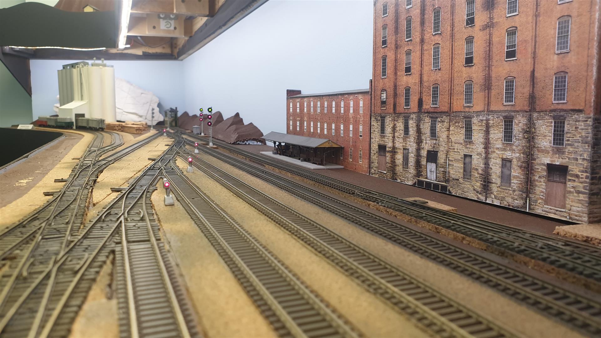
Here is a view of the signals installed.


The colours of the signals can be seen from the top.

The N scale engineer view of the signals.
The signals have just been painted silver with black hoods. They were later pushed down into the hole to be at about track height or just above.

This is the end of the build of the South staging signals.

The north staging signals are normal dwarf signals as they can be seen and are at eye height.


Next the install of the rest of the signals on the layout.