Sunday 26 February 2012

CTC Panel and Signalling system
At the outset, one of my main givens was a fully automated signalling system. I wanted to represent, as accurately as possible, the CTC block signalling system used by the D&H in the late '60's to late '70's. I was lucky enough to find a original D&H rule book for the 1940's that contains all signalling aspects that the D&H used that I could replicate on my own railway.
One of my requirements was that the signalling system did not control the trains, it simply displayed each signal aspect of a given block that they are protecting like the railway wood.
As the D&H signals all have 3 search lights per track that they are protecting the number of possibilities for different aspects was large. In developing the CTC panel I simplified these somewhat and reduced the number of combinations down.. This was primarily due to the number of blocks I have between towns was much less than the real railroad. The D&H also uses the signal aspects to display speed requirements as well as occupancy.
In order to be able to have the CTC panel I needed input from the layout in terms of block occupancy and also outputs in the form of signals.
As I had decided on Digitrax as my DCC system, I then started to look at the various products that are on the market that provide both block occupancy as well as signal drivers and the signal masts themselves.

Block Occupancy:
There are a number of block occupancy products on the market that range from the BDL168 that uses a bridge rectifier arrangement to detect trains to current sensing through coil arrangements.
In my earlier layout that I used to test some of these products I dabbled in a system that uses coils to detect current draw on the power for the track. This worked well but then needed to be connected to other boards that then provided the info on the Digitrax Loconet. In my testing I used the DS54 to bridge this gap and it worked ok.. But not as good and reliably as the BDL168.
All work very well, but the BDL168 came to the top of my list due to the cost per block was more effective than others. The BDL168 also has another feature that I utilise to drive other outputs that is not widely known (more on that later..) so the BDL168 was the occupancy detector of choice.

Signal heads:
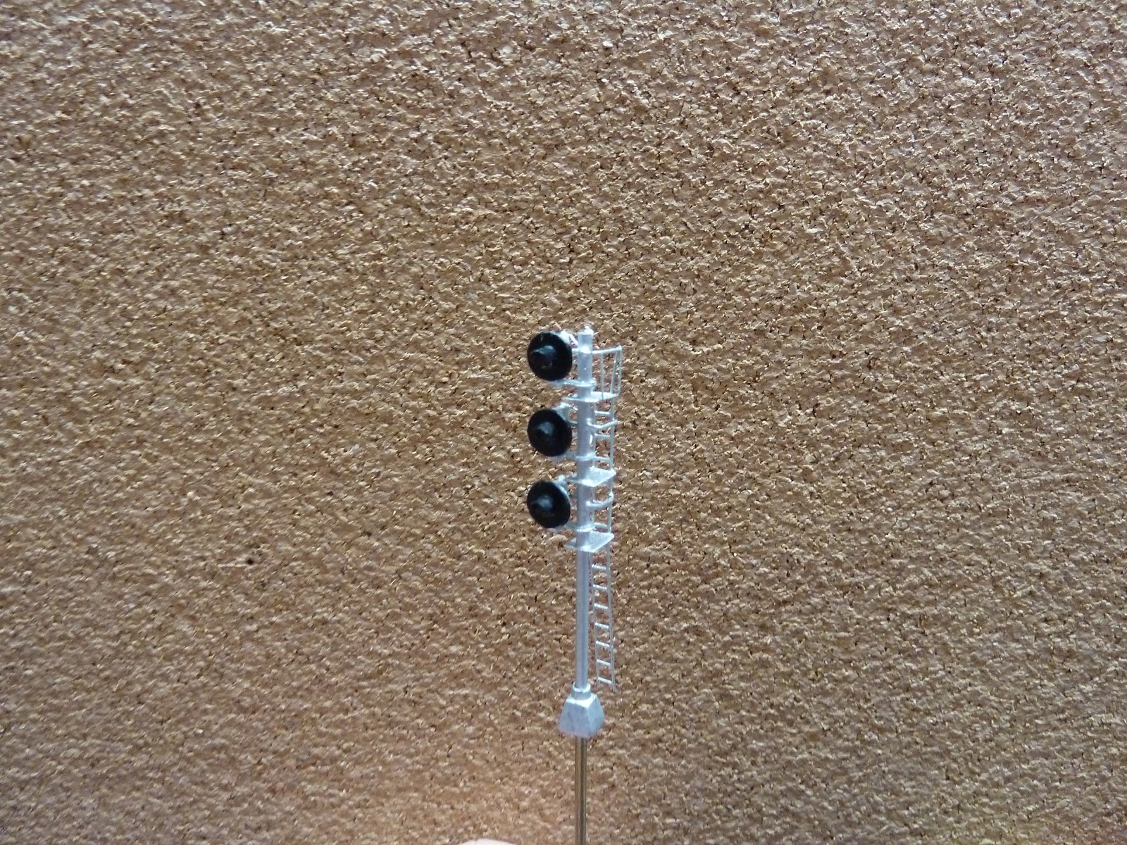
As I model the D&H, signal masts and heads that represent what the D&H use are not easy to come by, in fact they are next to impossible. So the only option I have is to scratch build them. Luckily I have a very good friend that is a master in design and brass etching. I was able to adapt his target signal head and ladders that are used for his west coast layouts into what I needed for the single mast 3 head signal units that I needed for the D&H. The D&H also use their own design in terms of tripple head dual mast designs (2 major variances) that I would also need to make. Over the last few years Vic and I have been working on a design that matches that of the D&H and am in the final stages of assembling the test etchings that I hope will work for my layout..


Signal Head Drivers:
TC-64..
As I wanted to represent the signalling rules of the D&H, off the shelf signal driver boards such as the Digitrax SE8C does not do what I needed to do. I then decided that if I wanted to represent D&H proto typical aspects I would need to fully develop those rules in a bunch of programming tasks within JMRI Panel Pro. Once I got my head around how JMRI works the rest took a bunch of trial and error and testing. Over time I managed to get JMRI Panel Pro to do what I wanted.
The other critical factor in driving signals is the hardware that interprets the info on the Loconet that panel pro is sending into a large number of outputs to drive the signal aspects.
I did a heap of research in this area as well and found that common cathode LED's was the most efficent way to driving low current draw outputs as all the hardware needed to do was current sinking and not current sourcing. This was a critical decision in the cost effectiveness of driving my signals. I found that a product called a TC64 from RR-Cirkits matched what I needed and it also can current sink its 5 v outputs with out any additional hardware or circuitry. I was then able to find a 2mm LED with a square back that matched my requirements being common cathode, 3 colour (Red, Green, Yellow) and 3 pin devices on the internet from a LED supplier. This would work perfectly for what I would need.


On the output of the TC64 I have also made a small board that is near the signal that holds the drop down resistors on it. This enables me to drive the Red and the Green at different voltages to obtain the colour I want.


BDL168:
Who would have thought that a BDL168 could be used for both block detection AND a signal driver. The BDL168 is primarily designed for block detection, it also has a LED output that can be used to check or monitor the occupancy of each block.. Upon further investigation of the BDL168 manual I found that the LED outputs can be decoupled from the Block detection part of the board and be used as individual outputs that can be controled directly from the loconet and therefore use Switch numbers to control them. I decided to give it a test with the tester board that comes with the BDL168. This worked a treat.. Given the output is really only designed to drive LED's at 1.5v and I wanted to be able to drive my signal LED's at differnt voltage / currents to get the right colour Yellow (from combining the Red and Green) I developed an additional circuit board that has 4 sets of 4 Optocoupler chips on it.

What is a opto coupler I hear you say..? It simply has a LED inside the device and a transistor that is turned on when the LED is turned on. As the LED and transistor are not electrically connected (See here http://en.wikipedia.org/wiki/Opto-isolator ) then the transistor can be run at any voltage while protecting the BDL168

This board has connector wires that come direct from the LED outputs of the BDL168 and then via the opto coupler a transisitor is used to drive the individual colour on the LED. I also use 330ohm at 5v for the green LED and 660ohm at 5v for the red LED. I found that if I use these resistance values I get a nice yellow when both LED colours are run at the same time.

Here is an example of the board I made.


The 40 pin cable that runs between the BDL168 and the board is disconnected to to make it easy to see the board.


After I had constructed the majority of the layout using older BDL162's (that I thought were BDL168's) I found that when more than 1 loco is run within the control of 1 BDL162 set of 16 outputs it can cause the BDL162 to give false readings on the other ports on the BDL162 when the supersonic motor control is enabled. This is a well known fault of the older BDL162 and while Digitrax did offer a upgrade program to the BDL168 at the time, by the time I had found the problem it was too late for the upgrade program. As I was committed to the Digitrax block detector I replaced the 4 x BDL162's with BDL168's. I was then faced with the dilema of what to do with the BDL162's that I could no longer use for block detection. However, because of my earlier investiations I knew that I could use them to drive my signals. So I kept theseemingly redundant BDL162's and made boards for them and also monitored the internnet for other people wanting to sell of get rid of their older BDL162's.. I now have a stock of them and will continue to use them to drive my signals.

Signals and output drivers needed. (oh the numbers.)
As all my D&H style signals have at least 3 LED's on them and up to 6, I knew that I was going to need a bunch of driver boards for my signals. When calculating out the number of outputs needed for the layout per my signal design, I found that as each LED would need 2 outputs (1 for the green and 1 for the red) from driver boards that would mean that each signal mast would need a total of 6 outputs for each set of 3. So for the places I needed the dual mast signal installments that the D&H used I would need a total of 12 outputs for each mast. If we then further calculate this out that would me that each interlocking that is a simple turn out into a loop this would mean that I would need 18 outputs. While not a big issue in terms of programming, the cost was a factor.. At this point I reviewed my signal aspect design and found that in 98% of cases the bottom signal aspect did not need to change from red if I elimiated some of the signaling rules that I did not really need. I then updated my plan and this would reduce the number of outputs needed to drive a single mast from 6 to 4 and from 12 to 8 for a double mast installment. This then mean that for each interlocking I would need only 12 outputs. While this does not seem a large difference, when you multiply them out and as I have at least 28 signal masts this would end up being at least 336 outputs needed to just drive the signals let alone the LED's on display panels etc. I think the decission to hard wire the bottom LED to be RED all the time was a wise move..

CTC Panel Version 1.
My first version of my JMRI CTC panel worked out well, although upon testing and a running session with my local crew of friends we found that seeing the track occupancy was a bit of a challenge..
So in order to fix this I changed from Panel Pro Panel editor to the Panel Pro layout editor..
This then enabled me to change the colour of the block of track that the train was occupying and thus enabled reading it to be much easier..
While this does not follow strict CTC panel protocol I thought it was a wise compromise.

Here is the first Panel.


Here is the current panel. This panel not only shows block occupancy but also shows the current aspect of each signal to make it easier for the CTC operator to see what is happening.
As you can see there are drawings for the signal leavers below the turnout leavers on the top and bottom sections. I have yet to program those so they are blank at present. So strictly speaking the panel and layout run the signals in ABS mode rather than true CTC. I plan on programing it in the future to be both..
 
Next time...
The prototype.. Why the D&H.
 

Saturday 25 February 2012

More Track Laying..
Now the staging was tested and I was happy with the results I then proceeded with more track laying and also layering of the next parts of the layout that would then form the main line..

As mentioned, I decided to use 3mm cork for my sub road bed on the 5ply timber.
By this time I had cut a large number of 15mm strips of cork for the sub road bed..
In order to get the track level looking right per the normal right of way, I marked where the track was to be placed, then used 2 pieces of 15mm cork side by side using the track middle line as the guide. I then glued this down with white glue and pins.. Then I used a second 3mm x 15mm strip of cork as the next layer to build up the sub road bed to give it that realistic high look ready for balasting in the future..

I also used the same method for the passing loops or sidings but I wanted to reduce the hight ever so slightly to give it a lower look.. I used the same 2 pieces of 3mm cork side by side and then used 1 strip of 1.5mm x 15mm cork to form the second or non main line track sub road bed. The end result is kind of neat..

In the main yard I decided to just use 1 full sheet of 3mm cork and not add the second 3mm or 1.5mm layer.. So the effect is that the main line is 3mm higher than the main yard and spurs with the passing loop being 1.5mm higher than the rest of the yard.

Here are a few progress shots...


By this time I am really enjoying this track laying gig..!

More Electricals..
In terms of power supply for the Digitrax DCS100 I use a old IBM Laptop docking station power supply that gives out 16V at 7.5A. Even though I only have a DCS100 I figured this would be more than ample and a nice smooth DC input for the input of the DCS100.. The power supply also has its own overload protection built in..
For the DS54, BDL168, UP5, UR92's and TC64's on the layout I use another IBM laptop power supply this time running at 16V DC and driving out 4.5A.. Again nice and smooth and has its own overload protection.. Use this power supply to drive all my acessories such as the Digitrax units and others as mentioned above. I dont have any issue with driving all of these from the same unit..
In terms of short protection on the layout I use DCC Specialties / Tony's Trains OG-CB's for the 3 power sub districts and I use the similar OG-AR's (solid state auto reversing management devices) for the 2 reversing loops I ahve on the layout.
Here are the OG-CB and OG-AR's along with the DCS100 power supply..

For the reverse loop on the end of the hidden staging I use DCC Specialties / Tonys Trains PSX-ARSC.. This great device is short protection, Auto reversing and also Solid State turnout driver board plus occupancy detection output..
I wired it to the reverse loop on the staging yard.. I placed 4 insulated joiners directly on the end of the #7 Atlas code 55 turnout and the H&M coil machine on the output of the snap coil machine section of the PSX-ARSC..
This great board then enabled me to wire in the reverse loop and the coil machine to the board.. I can then run a train into the reverse loop and just keep driving. The PSX-ARSC will detect when the train gets to the other end of the loop and crosses the gap on the turnout just next to the frog detects that the track section needs to be reversed, does the auto reverse and also throws the snap coil machine.. All within a milisecond..
So the end result is that the loco runs the gap, the reverser does the auto reverse and then thows the switch points all before the loco gets to the frog that is less than 5mm away. I can then just blindly set the staging for the empty track where the train is destined to go, run the traing all the way through staging, it goes around the loop the PSX-ARSC does its job, throws the turnout and the train then proceeds back into the same staging track it just left.. The engineer then waits for the train to come into view at the end of the staging track or sees a block dection indication light comes on and stops the train.. All with out needing to change a turn out. Just great..!

Next time..
First cut at CTC Panel and Block detection and Signal drivers..

Time for some track laying:
After much consultation with my local buddies and mentors I decided upon 3mm cork road bed directly on 12mm 5ply..
I then marked out the staging yard plan on the sub road bed and laid the cork.
Then it was down to the track work...
As the staging yard has a complex set up with 4 or 5 turnouts in a row I printed the section from the Atlas track planned and set up the turn outs on my work bench and soldered them together. Then I laid them out of the board and drilled the holes for the switch motors to be mounted under the layout.
I have always enjoyed laying track and this was no exception..
In order to keep the track on the cork, I used clear silicon as the glue to hold it in place.
On order to achive a thin consistancy I ruled a line as to where the track was to go, then run a narrow bead along the line and then used scrap cork to smooth the bead out to a very thin layer of silicon sealant.
As the silicon goes off in about 5 min I had a short period of time to get it right..
I used a long ruler to ensure that the track remained straight and used push pins to hold the track in place while the silicon dried.
The picture below shows the end of the staging with its return loop.. The return loop is to be automated but I will leave that info for another blog in the future..

Legs.... for construction..
As my future aim is to display the layout at local exhibitions I constructed the modules in such a way as to ensure that they all have legs.. All the legs are timber legs and are set up in the traditional way of 2 coach bolts and recessed nuts to hold them in place.. While this may be a time consuming exercise when setting up and pulling down at exhibitions, I figured that the number of exhibitions would probably be low so the low cost was the way to go.
The benifit of the legs also ment that I could use them during the construction phase of the layout in the garage.. As the layout does not need them when it is on its brackets when set up in the house the legs can then just be stored for future use.. You can see the legs in the picture above..

Test Run for the Staging loop.
Once I had completed the staging tracks, I then decided it was time for a test run.. I unbolted the 3 modules and took them inside..
The test went reletively well until I ran to Kato U30c's back to back around the end loop.. I then discovered that I had commited one of the cardinal sins of track laying and created a left, right combindation turns way too close to each other with out adding a straight section.. This then caused the longer loco's with body mounted couplers to bind and derail.. I soon found the issue and corrected it before it was too late (aka install of the layer of track above the staging yard..

As you may be able to see from the picture above, the return loop is fairly tight. As I needed it to be 9 1/2' radius I used Atlas code 55 9-1/2' curves to ensure no nasty joins.. As this section is hidden and going to be difficult to do any track maintenance I felt this was critical... On the rest of the layout I have only used Atlas code 55 set track for the joins between modules, turnouts (#7 and #6) and these tight curves. The rest I used normal Atlas code 55 flex.


Turn out control:
As I also enjoying in dabbling in electronics, and the fact that one of my givens was NO turn out switches on the front fascia. As I am not a fan of layout top manual ground throws and the Atlas code 55 turnouts need something to lock them in place I decided upon managing the turn outs via DCC and switch commands from the throttle or CTC panel.
I did a heap of research in this area and looked at what I had on hand from a earler test layout I had built, I decided that the majority of hidden switch mashines would be old H&M coil snap machines and be driven by Digitrax DS54's (as I some of these on hand). The H&M machines are a old machine that I had access to and make a decent "wack" sound when they thrown. Once these were combined with the approriate tension piano wire they are able to throw the Atlas turn out and keep them locked in place.

As part of my earlier test layout I found that the normal standard DS54 did not cope very well with the H&M coil machine power requirements. I then did a search and found a circuit on the internet that could be used in conjunction with the DS54 and effectively be a capacitor discharge unit on each output of the DS54 to drive the turnouts I have.. http://jean-louis.simonet.perso.neuf.fr/Ds54_CDU.pdf (all credit to Jean-Louis Simonet for the design and his assistance)

The info on the net from Jean-Louis provided circuit board etchings etc so I set to work. I then found a local circuit board etching company and had them etched.. Unfortunately they were not scaled quite correctly so they came out 1/3 plysically larger than what they needed to be but I was still able to install all the componenets and get it working.. (sorry for the quality of the picture)..


The benifit of the H&M's as mentioned means that you can hear the turnouts throwing in the staging with out seeing them.. (more on the management of routes and displays later..)

Next time...
In the next blog we will continue with track laying..

Start of construction

Mounting of the modules in the room.
Once the frames were assembled next came the test fit in the house where I was to co share the space with the kids.
In designing the mounting system for the brackets I wanted to minimise the effect on the walls for if / when the layout needed to be removed. As the walls had timber panelling I developed a system of top and bottom rails that were screwed into the panels. The screws went into the gaps in the pine to try and hide the holes once removed.
I then placed vertical timbers between these top and bottom rails to enable the l brackets to be screwed to the supporting (removable) timber.
Then along 1 wall we had IKEA cupboards that I had screwed to each other and made mounting brackets or stand offs so they would sit flush with the front of the layout.

Here are a few pictures of the 5 frames / modules all mounted on the brackets.


Track Plan Templates:
Once the frames were installed I then printed the entire track plan (from the Atlas Track planner) on A3 sheets of paper and taped them together. Then then enabled me to test the roadbed and the track layout to see if it was what I wanted.
This proved very effective, I was even able to take it to friends layout rooms and test to see how it would fit.


Wheels oh Wheels..!
As I had decided upon Atlas Code 55 track for the layout and the majority of my rolling stock is older cars from various manufacturers (collection started in the mid '70's) and given I had already converted all my stock to Microtrains trucks, I needed to change out all the pizza cutters to low profile. At the time I could not afford metal wheel sets so decided on the Atlas product that enables the Pizza cutters to be replaced by brown plastic wheels.. At the time I had approx 400 cars that needed replacing. So that task took a few nights / weeks..
I still have the jar full of Pizza cutter wheels as a memento.. (LOL)
Stay tuned for the next thrilling instalment...! Next time we will get down to laying track!.

Tuesday 14 February 2012

In the beginning.. There was a plan.!

Welcome to the D&H 2nd Sub blog.

As I started the layout planning and build back in 2008, I will do some catching up first and then will keep you all posted re the progress..

First some inspiration:


In order to start a layout build you need to have a list of givens and druthers..

The givens were:
N Scale
Delaware & Hudson
Time frame mid 60's to late 70's
Atlas code 55 flex track
Digitrax DCC
Full block monitoring
JMRI Panel Pro CTC panel
Co habitate with the kids in the play room
No switches or buttons on the layout fascia.
The layout must be transportable so I can take it to exhibitions
Siding lengths long enough for 2x 6 axel loco's, 12x 50ft cars and 1 caboose.
Hidden staging sidings

The Druthers:
Long runs between stations
Lots of scenery
Large yards
Lots of town switching..
And Im sure many more.
Large radius curves
#5 and #7 Atlas code 55 turnouts.
Tortoise machines to drive the turnouts.

After lots of time and discussions with the Melb Ntrak crew I came up with the following track plan..


Once the track plan was decided.. Work started..
I decided that the modules would be no longer than 1900mm long.
In order to co habitate with the kids in the play room I needed to keep the width to a minimum. So decided on 450mm wide on left side and 550mm side on top section. The design ended up with 5 modules that can be transported. I also added tongue and groove channels to the ends of the modules to locate them when put together. I also decided on the traditional bolt on legs. In terms of height.. The layout is 1340mm from the ground in the play room and higher when on legs.. When the layout is installed in the play room it sits on l bracket arms that are attached to the wall to enable the cupboards to be under the layout.


So, thats it for the first blog.. More to follow as I catch up from the work over the last 3 years..